| 1. Product Fundamentals |
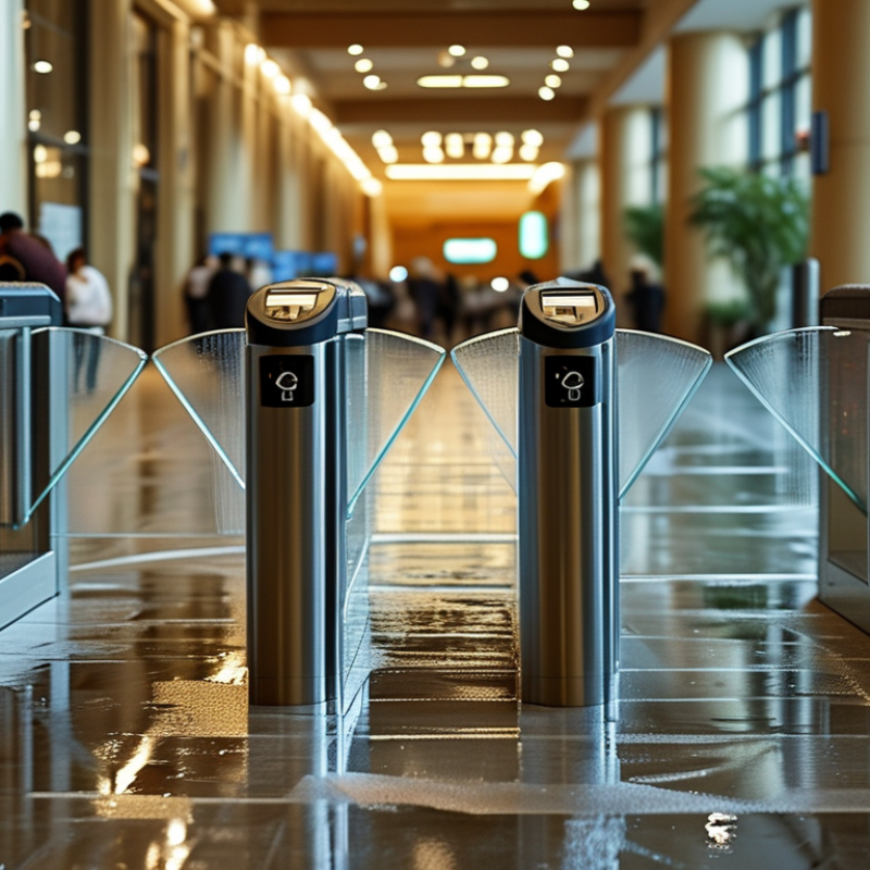
| Flap Turnstile Gate | A pedestrian access-control gate that uses one or two retractable panels, commonly called flaps, to open or close a passageway. | The flaps remain closed until an authorized access signal is received. After a valid credential is detected, the panels retract into the cabinet to create a passage. | Confirm the gate is intended for indoor use, sheltered outdoor use, or fully exposed outdoor installation. |
| Primary Purpose | To regulate pedestrian movement at controlled entrances and exits. | It combines physical access control with identity verification, passage counting, and unauthorized-entry prevention. | Match the gate type to the required security level, user volume, accessibility needs, and available floor space. |
| Common Applications | Office buildings, transit stations, airports, schools, universities, gyms, stadiums, public facilities, and residential properties. | The gate creates a defined pedestrian lane and can connect to card readers, QR-code scanners, biometric devices, ticketing systems, or visitor-management systems. | Check compatibility with the existing access-control, fire-alarm, building-management, and security-monitoring systems. |
| Passage Direction | Single-direction, bidirectional, or configurable directional operation. | Optical sensors and the controller determine whether entry, exit, or both directions are permitted. | Bidirectional operation is useful where the same lane handles both entering and leaving traffic. |
| 2. Operating Principles |
| Authorization Process | Credential presentation followed by access validation. | A reader sends the credential data to an access controller. If authorization is approved, the controller activates the gate motor and unlocks the lane for a preset period. | Verify reader interfaces such as Wiegand, RS-485, Ethernet, USB, relay input, or other required protocols. |
| Flap Movement | Motor-driven panels retract into or extend from the gate housing. | The drive mechanism moves the flaps smoothly while sensors monitor the open, closed, and obstruction positions. | Look for controlled acceleration, low operating noise, anti-pinch protection, and accessible maintenance components. |
| Passage Detection | Infrared or photoelectric sensors monitor the pedestrian position within the lane. | Sensors confirm that the authorized person has passed, prevent premature closing, and help detect tailgating or reverse movement. | More sensor zones generally provide better detection coverage, but correct installation and calibration remain essential. |
| Unauthorized Entry Response | Alarm, warning indicator, gate lock, or event notification when a person attempts to pass without authorization. | The controller compares sensor activity with the access event and can trigger an audible or visual alert. | Choose adjustable alarm behavior to reduce nuisance alerts in busy environments. |
| Power-Failure Behavior | Automatic opening, locked position, or battery-supported operation, depending on configuration. | The emergency mode determines whether the lane remains accessible or secured when normal power is unavailable. | For life-safety routes, the emergency release strategy must comply with local fire and accessibility regulations. |
| 3. Typical Technical Data |
| Typical Lane Width | Approximately 550–650 mm for a standard pedestrian lane; wider accessible lanes are commonly about 900–1,000 mm. | The lane width defines the usable passage and determines whether luggage, carts, wheelchairs, or mobility devices can pass. | Measure the site opening and select at least one accessible lane where required by local regulations. |
| Typical Cabinet Width | Approximately 100–200 mm per side for compact designs; larger dimensions may be required for readers, drives, and service access. | The cabinet houses the motor, control board, sensors, wiring, and retractable flap assembly. | Allow additional clearance for installation, cleaning, inspection, and component replacement. |
| Throughput | Typically about 25–35 persons per minute under controlled conditions, depending on credential and user behavior. | Throughput is influenced by the opening cycle, reader response time, lane width, queue design, and the percentage of users requiring assistance. | Use measured peak-hour demand rather than theoretical throughput when calculating the number of lanes. |
| Opening Time | Commonly about 0.5–1.2 seconds after a valid authorization signal, depending on the drive system and configuration. | A short opening cycle supports efficient movement while maintaining controlled access. | Ask for test results under normal load and confirm whether the stated time includes reader processing. |
| Input Voltage | Many systems use a low-voltage internal power supply fed from a site supply such as 100–240 V AC, subject to the equipment design. | The power supply converts incoming electricity for the controller, sensors, indicators, and motor. | Confirm the permitted voltage range, frequency, grounding requirements, surge protection, and local electrical certification. |
| Power Consumption | Often approximately 60–150 W during operation, with actual consumption varying by motor, heater, lighting, and standby design. | Energy is used by the controller, sensors, indicator lights, and motorized flap mechanism. | Request standby and peak operating values when estimating long-term energy use. |
| Operating Temperature | Indoor models commonly support approximately 0°C to 45°C; outdoor-rated models may support a wider range when properly specified. | Temperature limits protect electronic and mechanical components from unreliable operation. | For cold or humid locations, check heater, drainage, condensation control, and enclosure protection options. |
| Ingress Protection | Indoor units may have limited environmental protection, while outdoor installations often require a suitable IP-rated enclosure. | The enclosure rating indicates resistance to dust and water under defined test conditions. | Do not install an indoor model outdoors solely because its cabinet appears sealed; verify the complete system rating. |
| Expected Service Life | Quality systems are commonly specified for several million operating cycles, but the actual life depends on maintenance, traffic, and environment. | Each opening and closing movement contributes to mechanical wear in the motor, gears, sensors, and flap assembly. | Request the rated cycle count, test conditions, replacement-part availability, and warranty terms. |
| 4. Safety, Accessibility, and Security |
| Anti-Pinch Protection | Sensor-based or torque-based protection that stops or reverses flap movement when an obstruction is detected. | The system reduces the risk of trapping a person, bag, or mobility device during closing. | Check detection response, closing force, adjustable sensitivity, and compliance with applicable safety requirements. |
| Emergency Release | A fire-alarm input, emergency button, manual release, or automatic unlock function. | During an emergency, the gate can be configured to open or remain safely passable according to the building evacuation plan. | Have the emergency mode reviewed by the responsible fire-safety and facilities professionals. |
| Tailgating Detection | Detection of an additional person attempting to follow an authorized user through one access event. | Sensor data identifies unusual occupancy or movement and can trigger an alarm or event record. | Tailgating detection is affected by lane width, walking speed, crowding, and sensor placement. |
| Accessibility | Accessible configurations may include a wider lane, longer opening time, clear visual indicators, and compatible control devices. | The gate provides a safe route for wheelchair users, people with mobility aids, and users carrying bulky items. | Plan the accessible lane, approach space, threshold, signage, and emergency access together rather than selecting width alone. |
| Security Level | Flap gates provide controlled pedestrian access and visual deterrence but are not a substitute for a full-height barrier in every high-security application. | The barrier delays unauthorized passage while the access-control system verifies credentials. | For higher-risk sites, evaluate integration with guards, CCTV, anti-climb measures, mantrap layouts, and visitor procedures. |
| 5. Selection Checklist |
| Traffic Assessment | Record average flow, peak flow, queue length, entry-to-exit ratio, and credential presentation time. | Traffic data determines the required number of lanes and helps prevent congestion. | Consider special events, shift changes, school arrival periods, and cleaning or maintenance closures. |
| Integration Requirements | Access cards, QR codes, tickets, biometrics, facial recognition, visitor systems, alarms, and building-management interfaces. | Integrated systems allow authorization decisions, alarms, passage records, and emergency commands to be managed centrally. | Obtain interface documentation and confirm testing responsibility before purchase. |
| Installation Conditions | Assess floor flatness, anchoring surface, power route, network connection, drainage, lighting, and surrounding clearance. | Stable installation and correct sensor alignment are necessary for reliable flap movement and detection. | Request a site survey when the floor, traffic pattern, or environmental conditions are uncertain. |
| Maintenance Requirements | Routine cleaning, sensor inspection, fastener checks, software or controller testing, and replacement of worn components. | Preventive maintenance reduces downtime and helps preserve detection accuracy and opening performance. | Compare service intervals, technician access, spare-part lead times, and local support capability. |
| Recommended Documentation | Technical datasheet, installation manual, wiring diagram, safety instructions, test reports, warranty terms, and maintenance schedule. | Documentation supports correct installation, commissioning, troubleshooting, and compliance checks. | Do not finalize procurement until the documents cover the selected configuration and site conditions. |



 08045479132
 Send Inquiry

 Send Inquiry
 Send SMS