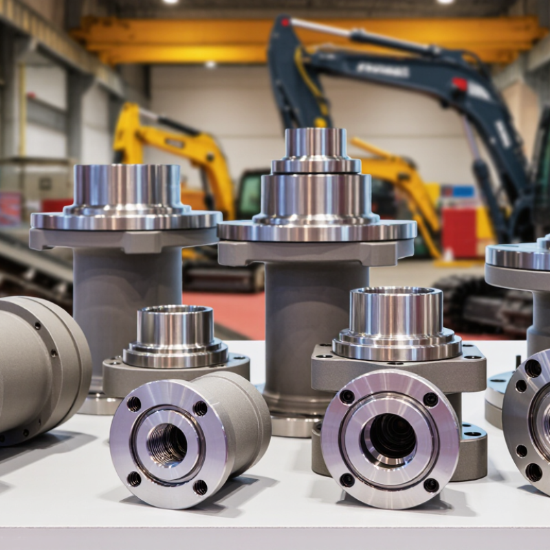
| Product Basics | Common Product Name | Hydraulic rotary center joint, center swivel joint, or central rotary joint | Used to transfer hydraulic oil between the stationary upper structure and the rotating lower structure of tracked construction equipment. |
| Product Basics | Primary Equipment | Hydraulic excavators, drilling rigs, forestry machines, demolition machines, and other crawler-mounted equipment | The correct product is selected according to equipment model, circuit arrangement, port layout, and installation dimensions. |
| Construction | Main Components | Housing, central spindle, manifold passages, thrust or radial bearings, seals, retaining rings, and mounting flange | The internal passages are designed to maintain hydraulic flow while allowing continuous or intermittent rotation. |
| Materials | Housing and Spindle | Commonly manufactured from alloy steel, carbon steel, or ductile iron with machined sealing surfaces | Material choice depends on working pressure, shock loading, corrosion conditions, required service life, and production cost. |
| Sealing System | Seal Materials | Nitrile rubber is widely used for general hydraulic oil; fluorocarbon rubber is used for higher-temperature or demanding fluid conditions | Seal compatibility should be checked against hydraulic fluid type, operating temperature, pressure pulsation, and contamination level. |
| Hydraulic Performance | Typical Working Pressure | Approximately 20 to 35 MPa for many excavator applications; the exact rating varies by circuit and design | The permitted pressure must be confirmed from the technical drawing or test certificate before installation. |
| Hydraulic Performance | Typical Peak Pressure | Often designed for short-duration pressure peaks above the normal working pressure, subject to the specified product rating | Pressure spikes can be caused by travel, swing, braking, blocked lines, or rapid changes in hydraulic load. |
| Flow Capability | Typical Flow Range | Approximately 30 to 250 L/min per passage, depending on port size, passage design, and equipment requirements | Insufficient flow capacity may increase pressure loss, heat generation, and operating inefficiency. |
| Port Configuration | Passage Quantity | Common configurations range from 2 to 12 hydraulic passages, with optional drain, pilot, or auxiliary passages | Port quantity and location must match the machine hydraulic schematic and the original mounting arrangement. |
| Port Configuration | Connection Types | Metric threaded, BSP, NPT, SAE flange, and other connection formats may be available depending on the equipment market | Thread type, sealing method, port orientation, and hose clearance should be verified before ordering. |
| Mechanical Design | Rotation Function | Allows hydraulic transmission during relative rotation between the upper and lower assemblies | The joint does not normally provide structural support for the complete machine; mounting loads must remain within the specified limits. |
| Mechanical Design | Rotation Speed | Normally matched to low-speed machine rotation, with the permissible speed determined by bearing, seal, and hydraulic design | Continuous rotation speed, intermittent operation, and reverse rotation requirements should be stated during technical evaluation. |
| Dimensional Control | Key Installation Dimensions | Overall height, outer diameter, mounting-hole circle, bolt-hole quantity, flange thickness, shaft diameter, and port spacing | A dimensionally interchangeable unit must match both the mechanical mounting pattern and the hydraulic passage arrangement. |
| Manufacturing | Production Processes | Forging or casting, CNC machining, heat treatment, grinding or finishing of sealing surfaces, assembly, and pressure testing | Stable machining accuracy and clean assembly conditions are important for preventing internal leakage and premature seal wear. |
| Quality Control | Recommended Tests | Dimensional inspection, material verification, low-pressure leakage testing, rated-pressure testing, rotation testing, and cleanliness inspection | Test requirements should be agreed in advance when the product is supplied for original-equipment replacement or export use. |
| Performance | Common Failure Symptoms | External oil leakage, internal leakage, abnormal pressure loss, slow actuator movement, overheating, and oil contamination | Diagnosis should also check hoses, fittings, hydraulic pumps, relief valves, filters, and incorrect installation before replacing the joint. |
| Service Life | Major Life Factors | Hydraulic cleanliness, pressure cycles, temperature, alignment, lubrication where applicable, seal quality, and maintenance practice | Service life is application-dependent and should not be estimated from operating hours alone. |
| Supplier Evaluation | Technical Documents | Dimensional drawing, port diagram, material information, pressure and flow ratings, installation instructions, and test records | Complete documentation reduces the risk of ordering a visually similar but functionally incompatible replacement. |
| Pricing Factors | Main Cost Variables | Passage quantity, size, material, machining complexity, seal specification, testing requirements, order quantity, and customization | A low purchase price should be evaluated together with compatibility, leakage risk, warranty terms, delivery time, and replacement cost. |
| Purchasing | Required Order Information | Equipment model, serial range, existing part reference, port count, pressure and flow data, installation dimensions, and application conditions | Providing complete information helps suppliers confirm the correct configuration and prepare an accurate quotation. |



 08045479132
 Send Inquiry

 Send Inquiry
 Send SMS