| Pump Construction and Operating Principle |
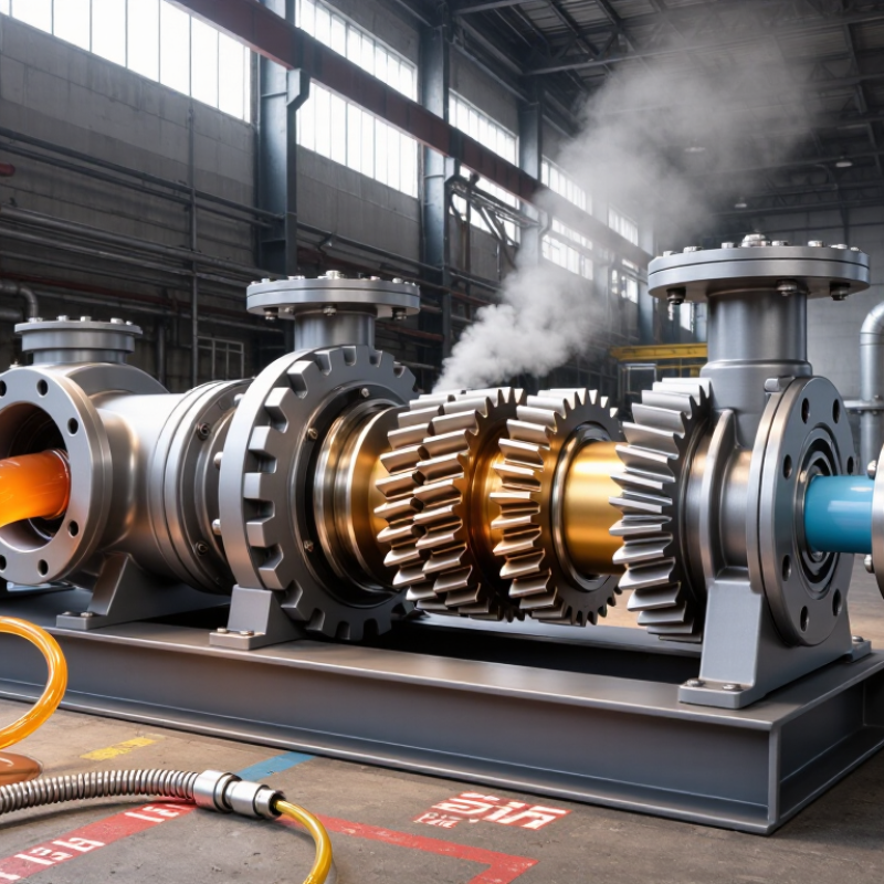
| Basic pump design | A positive-displacement pump containing two externally meshing helical gears inside a close-fitting housing. | One gear is driven; the second gear rotates through the meshing teeth. Fluid is carried in the spaces between the gear teeth and the casing. | Choose this design when a steady, low-pulsation flow is required and the fluid is compatible with close internal clearances. |
| Flow path | As the gears rotate, the expanding tooth spaces at the inlet create a partial vacuum. Fluid enters, travels around the outer circumference, and leaves when the tooth spaces mesh at the outlet. | Flow is generally proportional to rotational speed and pump displacement, subject to slip and operating conditions. | Confirm that the selected displacement produces the required flow at the available motor speed. Use a speed reducer or variable-speed drive when necessary. |
| Helical tooth profile | Gear teeth engage progressively along their width instead of contacting across the full width at once. | Typically provides smoother engagement, lower flow pulsation, and reduced noise compared with a similar straight-tooth external gear design. | Select helical gearing when acoustic performance, smooth discharge, or reduced vibration is important. Account for the axial thrust generated by the helix angle. |
| Positive-displacement behavior | The pump moves a defined volume per revolution, but actual output decreases when internal leakage, or slip, increases. | Flow is affected by pressure difference, fluid viscosity, speed, temperature, and internal clearances. | Do not select the pump using speed alone. Check the manufacturer's performance curve at the actual viscosity, pressure, and temperature. |
| Key Performance Requirements |
| Required flow rate | The volume of fluid that must be delivered per unit of time. | Common engineering units include L/min, m³/h, and US gal/min. The required value may be constant or variable. | Choose pump displacement and operating speed so the required flow is achieved without exceeding the recommended speed or pressure limits. |
| Displacement | The theoretical volume delivered per revolution. | Often expressed in cm³/rev or mL/rev. Theoretical flow can be estimated as: Q = displacement × speed. | Use a smaller displacement at higher speed or a larger displacement at lower speed. Include volumetric efficiency when estimating actual flow. |
| Operating pressure | The pressure the pump must develop to overcome system resistance and deliver the required flow. | Pressure capability depends on housing strength, gear geometry, shaft design, clearances, sealing, speed, and fluid viscosity. | Compare continuous and intermittent pressure ratings. Select a pump with an appropriate margin above the normal system pressure, while avoiding unnecessary oversizing. |
| Speed range | The allowable rotational speed of the pump shaft. | Higher speed can increase flow, but it may also increase wear, noise, heat generation, cavitation risk, and mechanical losses. | Verify minimum and maximum speed limits at the actual viscosity. A variable-frequency drive or gearbox may be needed to keep the pump within its recommended range. |
| Volumetric efficiency | The ratio of actual delivered flow to theoretical displacement flow. | Efficiency generally decreases as pressure rises and increases in many cases as fluid viscosity rises, provided the fluid remains pumpable. | Use tested performance data rather than the ideal displacement calculation when accurate flow control is required. |
| Mechanical and overall efficiency | Mechanical efficiency reflects friction losses; overall efficiency combines hydraulic, volumetric, and mechanical performance. | Efficiency varies with pressure, speed, viscosity, temperature, and clearances. | Use efficiency data to size the motor, estimate power consumption, and evaluate operating temperature. |
| Torque and motor power | The drive must supply enough torque to rotate the gears against system pressure and friction. | A simplified hydraulic power relationship is: Power (kW) ≈ pressure (bar) × flow (L/min) ÷ 600, before efficiency losses. | Apply the pump's actual efficiency and include a suitable service margin when selecting the motor, coupling, and gearbox. |
| Fluid Compatibility and Operating Conditions |
| Fluid viscosity | Viscosity affects lubrication, leakage, starting torque, and the ability of the pump to fill at the inlet. | External gear pumps are commonly used with lubricating and moderately viscous fluids. Very low viscosity increases slip; very high viscosity increases inlet losses and torque. | Check the permitted viscosity range at startup and operating temperature. Do not evaluate viscosity only at room temperature. |
| Fluid temperature | Temperature changes viscosity, seal life, material strength, and fluid compatibility. | Temperature limits are determined by the fluid, housing, bearings, shaft seals, elastomers, and lubrication conditions. | Select materials and seals for the maximum, minimum, and startup temperatures. Consider external heating or cooling for temperature-sensitive fluids. |
| Lubricity | Lubricity is the fluid's ability to reduce wear between gears, bearings, and other moving surfaces. | Lubricating oils generally provide better protection than water-like or poorly lubricating fluids. | For low-lubricity fluids, confirm suitable materials, reduced pressure or speed limits, and any required external lubrication arrangement. |
| Cleanliness and solids | Small clearances make external gear pumps sensitive to abrasive particles and contamination. | Solid particles can damage gear teeth, score the housing, increase internal leakage, and shorten seal life. | Install correctly sized filtration and specify a cleanliness level appropriate to the pump. Do not use the pump for slurry service unless it is specifically designed for it. |
| Chemical compatibility | The pumped fluid must be compatible with the housing, gears, shaft, bearings, seals, and coatings. | Compatibility depends on concentration, temperature, exposure time, and fluid additives. | Review a material-compatibility chart and verify elastomer selection. Water, solvents, acids, and aggressive chemicals may require special construction. |
| Entrained air and gas | Air or gas in the liquid can reduce volumetric performance, increase noise, and cause unstable flow. | External gear pumps are generally intended for liquids rather than high gas-content mixtures. | Minimize suction-line leaks, provide adequate inlet conditions, and use a degassing or air-separation arrangement when necessary. |
| Installation and System Design |
| Inlet conditions | The inlet must supply the pump with liquid at sufficient pressure to prevent excessive vapor formation and starvation. | Inlet losses increase with speed, fluid viscosity, restrictive filters, undersized piping, and long suction lines. | Use a short, adequately sized suction line; avoid unnecessary elbows and restrictions; and verify available NPSH or inlet pressure where applicable. |
| Cavitation risk | Cavitation occurs when local pressure falls below the fluid vapor pressure, causing vapor bubbles that collapse inside the pump. | Typical symptoms include rattling noise, vibration, reduced flow, and surface damage. | Reduce speed, lower fluid viscosity through controlled heating, enlarge the inlet line, clean the filter, or improve the liquid level and suction conditions. |
| Relief or bypass protection | A positive-displacement pump continues to generate flow when the discharge path is restricted. | Blocking the outlet can rapidly create excessive pressure and damage the pump, motor, piping, or seals. | Install a properly sized pressure-relief valve or another approved overpressure-protection device close to the pump discharge. |
| Rotation direction | Changing shaft rotation may change the inlet and outlet sides on some external gear pump designs. | Internal lubrication paths, thrust arrangements, and seals may be direction-dependent. | Confirm the permitted rotation direction before commissioning. Reverse rotation only when the pump is explicitly designed for it. |
| Mounting and alignment | The pump shaft, coupling, motor, and mounting base must be correctly aligned and supported. | Angular or parallel misalignment can increase bearing loads, vibration, seal wear, and coupling damage. | Use the specified coupling, check shaft alignment, avoid pipe loads on the pump ports, and provide adequate structural support. |
| Noise and vibration | Noise and vibration may result from gear meshing, pressure ripple, cavitation, misalignment, bearing wear, or inadequate support. | Helical gears generally reduce abrupt tooth engagement and can provide smoother operation, but they do not eliminate all noise sources. | Choose helical gearing for low-pulsation service, then address speed, inlet design, alignment, mounting stiffness, and pulsation control. |
| Materials, Sealing, and Maintenance |
| Gear and housing materials | Material selection determines resistance to wear, corrosion, pressure, temperature, and chemical attack. | Common constructions may include carbon steel, stainless steel, cast iron, and engineered materials, depending on the application. | Select materials based on fluid chemistry, cleanliness, pressure, temperature, required service life, and allowable contamination of the fluid. |
| Bearing arrangement | Bearings support the gear shafts and absorb radial and, in helical designs, axial loads. | Options may include internal plain bearings, rolling bearings, or externally supported arrangements. | Check load capacity, lubrication requirements, allowable contamination, and whether the pump can tolerate the expected axial thrust. |
| Shaft seal | The shaft seal prevents fluid leakage where the drive shaft exits the pump housing. | Seal options can include elastomeric lip seals, mechanical seals, packing, or magnetic-drive arrangements, depending on design. | Match the seal to fluid chemistry, temperature, pressure, shaft speed, emissions requirements, and leakage tolerance. |
| Internal clearance | The small gap between gears and the housing controls leakage and affects efficiency. | Tighter clearances can improve volumetric performance but may reduce tolerance to contamination, thermal expansion, and abrasive wear. | Choose a clearance configuration suitable for the fluid viscosity, temperature range, pressure, and cleanliness level. |
| Maintenance requirements | Maintenance typically includes inspection of seals, bearings, couplings, filters, pressure protection, and operating conditions. | Service intervals depend on duty cycle, fluid cleanliness, temperature, pressure, speed, and material selection. | Prioritize a design with accessible wear parts and available service documentation when downtime and maintenance access are critical. |
| Quick Selection Checklist |
| Application information to collect | The pump should be selected from complete operating data rather than from flow rate alone. | Required flow; normal and maximum pressure; speed range; fluid name and composition; viscosity at operating and startup temperatures; temperature; inlet conditions; solids content; rotation; and duty cycle. | Provide this information to the pump designer or supplier so the performance curve, materials, seals, and motor requirements can be checked at the actual duty point. |
| Best-fit applications | Helical external gear pumps are suited to clean or filtered liquids requiring steady, metered, and relatively low-pulsation flow. | Typical uses include lubrication systems, fuel and oil transfer, hydraulic power units, chemical metering of compatible liquids, and polymer or coating circulation. | Consider another pump technology when the fluid contains substantial solids, has very low lubricity, requires high suction lift, or contains a large amount of entrained gas. |
| Final verification | The selected pump must meet performance, safety, compatibility, and installation requirements simultaneously. | Always verify final ratings and limits against the pump manufacturer's technical documentation for the exact model and configuration. | Confirm flow at operating conditions, pressure rating, speed limits, motor power, inlet performance, seal compatibility, relief protection, and installation requirements before purchase. |



 08045479132
 Send Inquiry

 Send Inquiry
 Send SMS