| Pipe size and outside diameter | Confirm the nominal pipe size and outside diameter before selecting the flange bore and weld-end preparation. | NPS 2 pipe
Outside diameter: 60.3 mm | The flange bore and pipe OD must be compatible. Do not identify the pipe by nominal size alone. |
| Pipe wall thickness | Verify the schedule or specified wall thickness against the approved piping specification and design calculations. | NPS 2, Schedule 40
Nominal wall: 3.91 mm
Approximate ID: 52.5 mm | Measure actual wall thickness where required. The weld procedure, heat input, and joint fit-up must suit the actual thickness. |
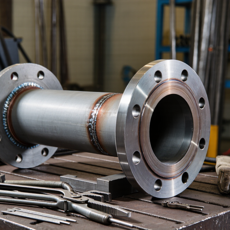
| Flange standard and pressure class | Use ASME B16.5 for pipe flanges and flanged fittings from NPS 1/2 through NPS 24. Confirm the class and material group. | ASME B16.5
NPS 2, Class 150
Welding neck, raised face | “Class 150” is a pressure-temperature designation, not a fixed 150 psi allowable pressure. Check the applicable B16.5 material pressure-temperature table. |
| Flange dimensions | Verify outside diameter, bolt circle, bolt-hole quantity, bolt-hole diameter, thickness, facing, and bore against the applicable ASME B16.5 table. | Typical NPS 2 Class 150 reference dimensions:
Outside diameter: 152.4 mm
Bolt circle: 120.7 mm
Bolting: 4 × 15.9 mm nominal bolts
Raised-face height: approximately 1.6 mm | Use the flange manufacturer’s certified dimensional drawing and the current ASME B16.5 edition for final inspection. Bore dimensions may vary with the connected pipe wall and flange series. |
| Flange material | Confirm the material specification, grade, heat number, and pressure-temperature rating. ASME B16.5 provides dimensional and rating requirements; it does not replace the material specification. | Carbon-steel example:
Forged flange material: ASTM A105N
Material certificate: required | Match the flange material to the piping design, service temperature, corrosion requirements, and approved material list. Confirm heat treatment and impact-test requirements when applicable. |
| Pipe material | Verify the pipe specification, grade, heat number, wall thickness, and condition before welding. | Carbon-steel example:
Pipe material: ASTM A106 Grade B
NPS 2, Schedule 40 | Check that the pipe and flange materials are approved as a compatible weld combination by the qualified welding procedure. |
| Butt-weld end preparation | Use ASME B16.25 for butt-welding-end dimensions and tolerances, including bevel configuration and alignment requirements. | Common carbon-steel preparation reference:
Included bevel angle: approximately 75°
Bevel angle per side: approximately 37.5°
Root face and root gap: as specified by the qualified WPS | Do not rely on a generic bevel value for every wall thickness. Measure bevel angle, root face, root opening, hi-low, and flange squareness before welding. |
| Welding process and filler metal | Select the process and filler metal using an approved WPS qualified in accordance with the project’s governing welding code, commonly ASME BPVC Section IX. | Example process: GTAW root / SMAW fill and cap
Example filler: AWS E7018 for compatible carbon-steel fill and cap passes | Filler selection must be confirmed by the WPS, base-metal group, service conditions, hydrogen-control requirements, preheat, interpass temperature, and post-weld heat-treatment requirements. |
| Weld consumable control | Control consumable identification, storage, drying, exposure time, and batch traceability according to the applicable specification and approved welding procedure. | Low-hydrogen electrodes such as E7018 require controlled storage and rebaking or holding conditions when specified by the project procedure. | Record electrode classification, lot number, issue time, storage temperature, and welder identification where required. |
| Flange alignment and orientation | The flange face must remain square to the pipe axis and the bolt-hole orientation must match the installation drawing. | Inspection points:
Face squareness
Angular rotation
Pipe projection
Internal bore transition | Prevent excessive forced fit-up. Verify bolt-hole orientation before tack welding, and protect the raised face from arc strikes, spatter, and distortion. |
| Pre-weld and post-weld inspection | Inspection scope is governed by the project specification, design code, and approved inspection and test plan. | Typical checks:
Visual examination: 100%
Dimensional inspection: before and after welding
NDE: as specified, such as RT, UT, MT, or PT | Confirm weld profile, undercut, surface defects, flange distortion, bore condition, and final dimensional compliance before pressure testing or service. |



 08045479132
 Send Inquiry

 Send Inquiry
 Send SMS