What Is a PCB Control Board and How Does It Work?
A Pcb Control Board is the operating center of many electronic products. It receives signals, processes instructions, and controls connected components. Inside, copper traces carry electrical signals between chips, sensors, relays, connectors, and power circuits. A microcontroller may read a temperature sensor, compare the result with programmed limits, and activate a fan. The process happens quickly, often without visible movement. Small decisions matter.
In practical equipment, the board also manages voltage regulation, communication, protection, and fault detection. Engineers study the schematic, component ratings, firmware behavior, and manufacturing quality before approving a design. They may inspect solder joints, measure supply rails, and test the board under heat or vibration. These checks connect laboratory theory with real operating conditions. A reliable Pcb Control Board should perform consistently, not only during a short demonstration.
However, no control board is perfect. Heat, moisture, electrical noise, and aging components can expose weak design choices. A connector may loosen. A software assumption may fail. That uncertainty deserves attention. Good engineers document risks, verify measurements, and improve designs through testing. This article explains how a Pcb Control Board works, from signal input to controlled output. It also considers the practical decisions behind dependable operation, including circuit layout, protection methods, maintenance, and troubleshooting. The goal is a clear technical foundation for readers who want to understand what happens beneath a machine’s enclosure.
What Is a PCB Control Board?
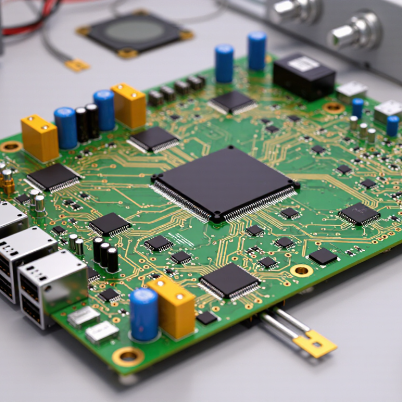
A PCB control board is a populated circuit board that manages electrical functions inside equipment. It combines copper traces, integrated circuits, sensors, connectors, relays, and sometimes a microcontroller. The PCB provides the physical structure. The control logic decides what happens next. For example, a temperature sensor may send a changing voltage to the controller. The controller compares that signal with programmed limits. It then switches a motor, valve, display, or alarm.
The term is not perfectly standardized. Some engineers use “control board” for the complete assembly, while others mean only the bare PCB. That distinction matters during testing and maintenance. A bare board cannot perform its intended task without components and firmware. According to Grand View Research, the global PCB market was valued at about $89.7 billion in 2023, with projected growth of 5.6% annually from 2024 to 2030. This expansion reflects growing demand for compact, reliable control electronics. Yet size alone does not prove quality. IPC design guidance emphasizes spacing, material selection, thermal control, and manufacturability. In practice, a board may pass an electrical test but still suffer from heat buildup or difficult servicing. Good control-board design considers signals, power, protection, and real-world access from the beginning.
What Is a PCB Control Board and How Does It Work?
A PCB control board is a printed circuit board that receives input signals, processes them with electronic circuits or a microcontroller, and drives outputs such as motors, relays, displays, or communication interfaces.
Representative Voltage Domains in PCB Control Boards
Different sections of a control board may use different nominal voltage domains. A 24 V domain is common for industrial power and I/O, while 5 V, 3.3 V, and 1.8 V are widely used for logic, sensors, and digital processing. Voltage regulators, isolation circuits, and level shifters allow these sections to work together safely.
How Does a PCB Control Board Process Signals?
What Is a PCB Control Board and How Does It Work?
A PCB control board processes signals through a clear electrical sequence. Sensors first convert temperature, pressure, motion, or position into voltage, current, or digital pulses. Signal-conditioning circuits then filter noise and adjust the level. An analog-to-digital converter samples the signal before a microcontroller interprets it. According to the Nyquist-Shannon sampling principle, the sampling rate should exceed twice the highest signal frequency. Real designs often add margin because motors, relays, and long cables create unexpected interference.
The controller compares measured data with programmed limits. It may calculate speed, detect an overcurrent event, or adjust a valve through pulse-width modulation. A digital output then drives a relay, transistor, or power module. The U.S. Department of Energy reports that electric motor systems consume roughly 46% of global electricity, making accurate control signals important for industrial efficiency. Even a small timing error can produce vibration, heat, or unstable operation. That detail is easy to underestimate.
Practical boards also monitor their own condition. Watchdog timers detect software stalls, while isolation barriers separate low-voltage logic from hazardous power sections. IPC design guidance emphasizes controlled impedance, grounding, thermal management, and manufacturing inspection. Yet standards cannot remove every uncertainty. A prototype may pass bench testing and fail beside a switching motor. Engineers should test noise, temperature, load changes, and connector vibration under realistic conditions. The first design is rarely perfect. Reflection matters.



 08045479132
 Send Inquiry

 Send Inquiry
 Send SMS