What Is a Pipe Swaging Machine and How Does It Work?
A Pipe Swaging Machine reshapes a tube’s end by reducing, expanding, or forming its diameter through controlled pressure. The process can create stepped ends, tapered sections, sockets, and connection-ready profiles. In a typical workshop, a straight tube enters a die, aligns against a stop, and receives repeated radial force. The die closes gradually. Material flows rather than simply being cut away.
This matters because tube manufacturers face constant pressure to improve material use, repeatability, and production speed. The World Steel Association’s Short Range Outlook 2024 projected global finished steel demand at approximately 1.75 billion tonnes in 2024. That scale highlights the importance of efficient forming methods across construction, automotive, energy, and industrial equipment. A machine that reduces scrap can influence both production cost and environmental performance.
The working principle is precise, but not effortless. Operators must match die geometry, tube grade, wall thickness, lubrication, and forming speed. Small errors can produce ovality, wrinkles, surface marks, or uneven wall reduction. These defects may remain hidden until welding or assembly. That is why experienced manufacturers verify dimensions with calipers, gauges, and coordinate measuring equipment.
Technical guidance from ASM International’s metal-forming references emphasizes material behavior, work hardening, and controlled deformation. ISO dimensional standards also support consistent inspection practices. Still, no report replaces practical judgment. Every alloy behaves differently. A reliable Pipe Swaging Machine therefore combines rigid tooling, stable hydraulic or mechanical force, accurate alignment, and disciplined quality control. The technology is straightforward to describe. Mastering it is harder.
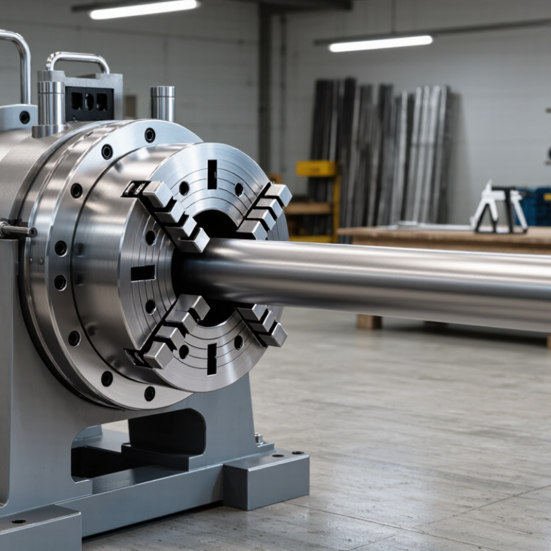
What Is a Pipe Swaging Machine?
A pipe swaging machine is industrial equipment that reshapes a pipe’s end without removing its material. It reduces or forms the outside diameter to create a precise connection. The machine uses dies, pressure, and controlled movement. Unlike ordinary cutting, swaging changes the pipe’s geometry while keeping its structure largely continuous.
A pipe is placed inside a correctly sized die or tooling set. The machine then applies radial force around the pipe. Some models use hydraulic pressure, while others use mechanical or rotary motion. The tooling gradually compresses the metal into the required profile. This process can prepare ends for joining, sealing, or fitting into another component. Experienced operators check wall thickness, material type, and final dimensions before production. Small errors matter. A poorly matched die may leave marks, uneven walls, or an unreliable fit. In practice, the first setup may need adjustment, and that is easy to underestimate.
Tips: Measure the pipe before and after swaging. Inspect the surface for cracks, wrinkles, or deep impressions. Keep dies clean and properly aligned. Use calibrated measuring tools and follow the machine’s operating instructions. Protective equipment also matters, especially around moving tooling and hydraulic systems. A trial piece is useful, but it does not replace careful process control.
How the Pipe Swaging Process Works
What Is a Pipe Swaging Machine and How Does It Work?
How the Pipe Swaging Process Works
A pipe swaging machine reshapes a tube by applying controlled force around its circumference. The process can reduce the outside diameter, form a taper, or create a joining section. Unlike cutting, swaging changes the metal’s shape while preserving most of its material.
The operator first checks the pipe’s diameter, wall thickness, length, and material grade. Surface dirt and burrs are removed before the tube enters the die. A suitable die is then installed and aligned with the machine axis. This step matters. Poor alignment can create uneven walls or a visibly crooked end.
The machine clamps the pipe and pushes it into the forming area. In rotary systems, several dies strike the pipe rapidly from different directions. In press systems, one controlled stroke compresses the tube inside a shaped die. Pressure must match the material and required reduction. Excessive force may cause cracks, wrinkles, or unwanted thinning. Insufficient force leaves an incomplete profile.
After forming, technicians measure the new diameter with calibrated gauges. They also check roundness, surface marks, wall thickness, and the transition between formed and unformed sections. A light lubricant can improve material flow, but too much may hide surface defects. In real workshops, the first setup is rarely perfect. Small adjustments to feed length, die clearance, or pressure often improve consistency.
What Is a Pipe Swaging Machine and How Does It Work?
Pipe swaging is a cold-forming process that reduces or reshapes the end of a tube or pipe by applying radial pressure with segmented dies. This example shows a common nominal size transition from a 1-inch tube to a 3/4-inch swaged end. The dies close progressively around the workpiece, forming the metal without cutting it and creating a smaller, tapered, or specially shaped end.
Industrial Applications and Operating Considerations
A pipe swaging machine reshapes a tube end by applying controlled radial pressure. Its dies compress the pipe without cutting away its material. The result may be a reduced diameter, tapered end, or joint-ready profile. Unlike machining, swaging can preserve more material and shorten production time. The 2024 World Steel Association report recorded 1.89 billion tonnes of global crude steel production in 2023. That scale highlights why efficient forming methods matter in metal-intensive industries.
Swaging is used for hydraulic lines, automotive exhaust parts, heat exchangers, construction tubes, and selected aerospace components. Operators choose tooling according to alloy, wall thickness, diameter, and required reduction. Stainless steel often needs slower forming and careful lubrication. Aluminum usually forms more easily, but it can mark under excessive die pressure. Small details matter. A misaligned tube may leave uneven wall thickness or unwanted ovality. These defects can appear only after assembly or pressure testing.
Operating discipline protects both quality and equipment. Measure the tube before and after each trial run. Check surface cracks, end geometry, and springback. Keep dies clean and inspect them for wear. The U.S. Department of Energy notes that compressed-air leaks can waste 20–30% of compressor output, so pneumatic auxiliaries deserve attention. Hydraulic systems also require clean fluid and stable pressure. In practice, the first setup is rarely perfect. A rushed adjustment may pass one inspection and fail later. Recording force, stroke, lubrication, and inspection results makes troubleshooting more reliable.



 08045479132
 Send Inquiry

 Send Inquiry
 Send SMS